Welcome to the first post in my Engineering Blog! I am always working on something interesting, it seems, and I plan to post the most interesting events, surprises, failures, and successes right here. I’ll guess the failures will be more entertaining than the rest, but let’s get down to business:
I recently was asked to diagnose repeated failures in a set of high-voltage driver amplifiers for a local R&D firm. Their customer had installed the units, only to have many of them fail shortly after they were placed in service. Chips failed, were replaced, and failed again.
At first, opening the chassis did not reveal anything obvious, nor did the traditional probing around looking for component or wiring failures. So, I broke out the digital microscope. I saw some mechanical damage to a few capacitors, but this did not explain the symptoms. Searching deeper, I found a small ‘scar’ on one solder joint of a large driver transistor. It looked like an electrical arc had taken place, but no other components were nearby. At least I thought so until I began connecting the dots.
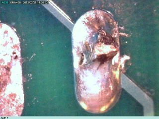
The mechanical damage on the capacitors was being caused by contact with a mounting screw head which passed by as the amplifier circuit board was installed in its case. 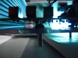 With the circuit board seated in the chassis, the screw head ended up underneath the ‘scar’, and I had my answer. The screw head represented a chassis ground point places in very close proximity to a high voltage node of the circuit, and when the amp was cranked up, it arced over. Just a few of these arcs was enough to damage the transistors and cause amplifier failure.
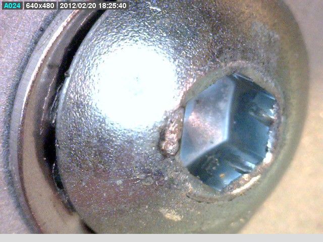
A simple fix, though: Flat head screws instead of round heads!


